GayMePy Gay Python Guide in Computational Chemistry
PyAdjust - my very first PyMOL API

Konnichiwa minasan! Salut tout le monde! Olá Pessoal!¡Hola todos! Hi everybody! Yeah, I know it seems like almost an entire year since my last publication. Actually, my life has been quite challenging since this COVID thing and so many things happening at the same time. Well, I’ve been through a lot recently and working as there is no tomorrow. But hey, at least I’m managing to survive despite all the life-challenging scenarios we are facing.
If you excuse me, I would like to give you all a sense of what is happening, and why I’m going with this publication right now. I’ve been thinking and working on an awful lot of projects to publish here to suit me as a portfolio as well. However, I’ve not been happy with my results. Then, in a calling to my mum (yes folks, I do call my mum often) she told me something worth thinking about: if you wait for the right time for doing something, it will never happen. Well, actually we were talking about having children, but the saying worth it for other aspects of my life such as this humble website.
Soooooooooooo, after all this, I decided to embark on a little project that I thought about several times. I got a chance to visit a friend of mine in Poland and took the spare time I had to start this. First, I was willing to create an application programming interface (API) in Python for PyMOL. What I was looking for was something simple. As I work a lot with crystal structures having periodic boundary conditions (PBC), it would help me a lot if PyMOL could deal with that allowing me to move things around at the same time it keeps the structure within its PBC.
By following the advice we get over time, I decided to start from scratch and by doing it simple at first, for I’ve no previous knowledge in doing APIs for PyMOL. So, I started learning from the PyMOLWiki page, which gave me a sense of what to do. It uses Qt as the main graphical user interface (GUI) designer, which I had some working skills. So, it seemed straightforward to do what I wanted. First of all, I idealized what the API would look like, something that resembles figure 1.
![PyAdjust - GUI \[*_*]/. PyAdjust - GUI](https://mvfbarrionuevo.github.io/GayMePy/images/pyadjustgui.png) Figure 1: First view of PyAdjust - GUI.
Figure 1: First view of PyAdjust - GUI.
Sure thing, one can obtain that by using Qt Designer. However, I had no extra patience learning more things about Qt, and I ended up doing most of it by hand with the little I know about Qt user interface. For the sake of convenience, I’ll not show the written Qt code as it can be found here.
With that in place, I moved to the core function of my idea. The function would take a 3D point in space and set that as the middle of the PBC box. However, that should be done only in one plane at a time. For now, I decided to do that in the XY plane, since for most of my purposes I’m not interested in moving along the z-axis. The good news is changing/adapting the existing code now on will be easy-breeze. So, assuming I know the cell matrix for the PBC system and the point I want to set as the center of the XY-plane, all I will need is the code below:
from numpy import linalg, array

def centralize_xy(cell, positions):
    point = array([float(form.at_x.text()), \
                   float(form.at_y.text()), \
                   0.], dtype = float)
    centre = (cell[0] + cell[1])/2
    d = point - centre
    positions -= d
    icell = linalg.inv(cell)
    ipos = positions.dot(icell)
    for i, row in enumerate(ipos):
        for j, c in enumerate(row):
            if c >= 1.: ipos[i, j] -= 1
            if c < 0.: ipos[i, j] += 1
    for i, row in enumerate(ipos):
        if row[2] > .98: ipos[i, 2] -= 1.
    return ipos.dot(cell)
As you can see, I have called for linalg library from NumPy, that is real important for applying PBC correction. But just for a start, notice that I set the center (and I wrote it as centre, because I like this to be Canadian written) as the middle of the XY-plane, then compute the distance from my point and subtracted that from all positions. With that simple approach one manages to get everything adjusted as desired, but falls off the PBC. So, for fixing it the inverse matrix of the cell is needed to compute the relative positions of every atom concerning the cell matrix. The relative position is easily computed as the dot product of the positions by the inverse cell matrix that defines the crystal cell. Hence, a simple loop will decide which axis is falling off the cell matrix. Isn’t that cute? Simple, yet powerful.
Well, this is it. Now I have the core function in place and it shall work for any scenario, no matter what kind of crystal cell I have. Also, I thought it would be cool to just draw the cell of the system once you have given to it the cell matrix (see figure 1). For doing that, a more cumbersome code was needed. Despite it seemingly ugliness at first sight, it is bafflingly simple. The code looked like this:
from pymol.cgo import LINEWIDTH, BEGIN, LINES, \
                      COLOR, VERTEX, END

cell = array([[form.ax.value(), form.ay.value(), form.az.value()], \
              [form.bx.value(), form.by.value(), form.bz.value()], \
              [form.cx.value(), form.cy.value(), form.cz.value()]], \
             dtype = float)

b_yx = cell[0] + cell[1]
t_zx = cell[0] + cell[2]
t_zy = cell[1] + cell[2]
t_yx = cell.sum(axis = 0)

PBC_BOX = [ \
    LINEWIDTH, 1, BEGIN, LINES, \
    COLOR, 0., 0., 0., \

    VERTEX, 0.0, 0.0, 0.0, \
    VERTEX, cell[0, 0], cell[0, 1], cell[0, 2], \

    VERTEX, 0.0, 0.0, 0.0, \
    VERTEX, cell[1, 0], cell[1, 1], cell[1, 2], \

    VERTEX, 0.0, 0.0, 0.0, \
    VERTEX, cell[2, 0], cell[2, 1], cell[2, 2], \

    VERTEX, cell[0, 0], cell[0, 1], cell[0, 2], \
    VERTEX, b_yx[0], b_yx[1], b_yx[2], \

    VERTEX, cell[1, 0], cell[1, 1], cell[1, 2], \
    VERTEX, b_yx[0], b_yx[1], b_yx[2], \

    VERTEX, cell[2, 0], cell[2, 1], cell[2, 2], \
    VERTEX, t_zx[0], t_zx[1], t_zx[2], \

    VERTEX, cell[2, 0], cell[2, 1], cell[2, 2], \
    VERTEX, t_zy[0], t_zy[1], t_zy[2], \

    VERTEX, cell[1, 0], cell[1, 1], cell[1, 2], \
    VERTEX, t_zy[0], t_zy[1], t_zy[2], \

    VERTEX, t_zy[0], t_zy[1], t_zy[2], \
    VERTEX, t_yx[0], t_yx[1], t_yx[2], \

    VERTEX, t_yx[0], t_yx[1], t_yx[2], \
    VERTEX, t_zx[0], t_zx[1], t_zx[2], \

    VERTEX, cell[0, 0], cell[0, 1], cell[0, 2], \
    VERTEX, t_zx[0], t_zx[1], t_zx[2], \

    VERTEX, b_yx[0], b_yx[1], b_yx[2], \
    VERTEX, t_yx[0], t_yx[1], t_yx[2], \

    END \
]
cmd.load_cgo(PBC_BOX, 'PBC_CELL')
As one can see, first a few special values is needed from the PyMOL CGO library, then we need to retrieve again the cell matrix and decide where are the bottom (b) and top (t) 3D cartesian position of the yx, zx, zy and yx corners. Once that is done, we simply glue them together in the set of commands following the PyMOL CGO standard. I’ll leave it here for you to have a look at my code, and realize why do we need 24 VERTEX declarations.
After all that, the only thing missing is the actual connection between the GUI and my functions. For that, I followed the PyMOLWiki instructions, and placed everything together as:
'''
PyAdjust
Author: Manoel Victor Frutuoso Barrionuevo
Contact: manoelvfb@live.ca
Date: 23/01/2022
DOI: 10.5281/zenodo.5895106
'''

from __future__ import absolute_import
from __future__ import print_function
from os import path

# Avoid importing "expensive" modules here (e.g. scipy), since this code is
# executed on PyMOL's startup. Only import such modules inside functions.

def __init_plugin__(app=None):
    '''
    Add an entry to the PyMOL "Plugin" menu
    '''
    from pymol.plugins import addmenuitemqt
    addmenuitemqt('PyAdjust', run_plugin_gui)


# global reference to avoid garbage collection of our dialog
dialog = None

def run_plugin_gui():
    '''
    Open our custom dialog
    '''
    global dialog

    if dialog is None:
        dialog = make_dialog()

    dialog.show()

def make_dialog():
    from pymol import cmd
    from numpy import array, linalg
    from pymol.Qt import QtWidgets
    from pymol.Qt.utils import loadUi
    from pymol.Qt.utils import getSaveFileNameWithExt

    dialog = QtWidgets.QDialog()

    uifile = path.join(path.dirname(__file__), 'pyadjust.ui')
    form = loadUi(uifile, dialog)

    def draw_PBC():
        from pymol.cgo import LINEWIDTH, BEGIN, LINES, \
                              COLOR, VERTEX, END
        cell = array([[form.ax.value(), form.ay.value(), form.az.value()], \
                      [form.bx.value(), form.by.value(), form.bz.value()], \
                      [form.cx.value(), form.cy.value(), form.cz.value()]], \
                     dtype = float)

        b_yx = cell[0] + cell[1]
        t_zx = cell[0] + cell[2]
        t_zy = cell[1] + cell[2]
        t_yx = cell.sum(axis = 0)

        PBC_BOX = [ \
            LINEWIDTH, 1, BEGIN, LINES, \
            COLOR, 0., 0., 0., \

            VERTEX, 0.0, 0.0, 0.0, \
            VERTEX, cell[0, 0], cell[0, 1], cell[0, 2], \

            VERTEX, 0.0, 0.0, 0.0, \
            VERTEX, cell[1, 0], cell[1, 1], cell[1, 2], \

            VERTEX, 0.0, 0.0, 0.0, \
            VERTEX, cell[2, 0], cell[2, 1], cell[2, 2], \

            VERTEX, cell[0, 0], cell[0, 1], cell[0, 2], \
            VERTEX, b_yx[0], b_yx[1], b_yx[2], \

            VERTEX, cell[1, 0], cell[1, 1], cell[1, 2], \
            VERTEX, b_yx[0], b_yx[1], b_yx[2], \

            VERTEX, cell[2, 0], cell[2, 1], cell[2, 2], \
            VERTEX, t_zx[0], t_zx[1], t_zx[2], \

            VERTEX, cell[2, 0], cell[2, 1], cell[2, 2], \
            VERTEX, t_zy[0], t_zy[1], t_zy[2], \

            VERTEX, cell[1, 0], cell[1, 1], cell[1, 2], \
            VERTEX, t_zy[0], t_zy[1], t_zy[2], \

            VERTEX, t_zy[0], t_zy[1], t_zy[2], \
            VERTEX, t_yx[0], t_yx[1], t_yx[2], \

            VERTEX, t_yx[0], t_yx[1], t_yx[2], \
            VERTEX, t_zx[0], t_zx[1], t_zx[2], \

            VERTEX, cell[0, 0], cell[0, 1], cell[0, 2], \
            VERTEX, t_zx[0], t_zx[1], t_zx[2], \

            VERTEX, b_yx[0], b_yx[1], b_yx[2], \
            VERTEX, t_yx[0], t_yx[1], t_yx[2], \

            END \
        ]
        cmd.load_cgo(PBC_BOX, 'PBC_CELL')
        return True

    def pick():
        selected = False

        refer = cmd.get_coords('sele')

        if refer is not None:
            size = len(refer)
            if size >= 2:
                refer = refer.sum(axis = 0)/size
            else:
                refer = refer[0]
            selected = True

        else:
            print('First, click over the atom(s) you want.')

        if selected:
            form.at_x.setText(f'{refer[0]:10.6f}')
            form.at_y.setText(f'{refer[1]:10.6f}')
            form.at_z.setText(f'{refer[2]:10.6f}')

    def run():
        def centralize_xy(cell, positions):
            point = array([float(form.at_x.text()), \
                           float(form.at_y.text()), \
                           0.], dtype = float)
            centre = (cell[0] + cell[1])/2
            d = point - centre
            positions -= d
            icell = linalg.inv(cell)
            ipos = positions.dot(icell)
            for i, row in enumerate(ipos):
                for j, c in enumerate(row):
                    if c >= 1.: ipos[i, j] -= 1
                    if c < 0.: ipos[i, j] += 1
            for i, row in enumerate(ipos):
                if row[2] > .98: ipos[i, 2] -= 1.
            return ipos.dot(cell)

        cell = array([[form.ax.value(), form.ay.value(), form.az.value()], \
                      [form.bx.value(), form.by.value(), form.bz.value()], \
                      [form.cx.value(), form.cy.value(), form.cz.value()]], \
                     dtype = float)
        obj = cmd.get_object_list('all')[0]
        positions = cmd.get_coordset(obj)
        new_positions = centralize_xy(cell, positions)
        for i, row in enumerate(new_positions):
            cmd.alter_state('1', f'rank {i}', \
                            f'(x, y, z) =  ({row[0]}, {row[1]}, {row[2]})')
        pick()

    form.button_PBC.clicked.connect(draw_PBC)
    form.pick_atom.clicked.connect(pick)
    form.button_adjust.clicked.connect(run)

    return dialog
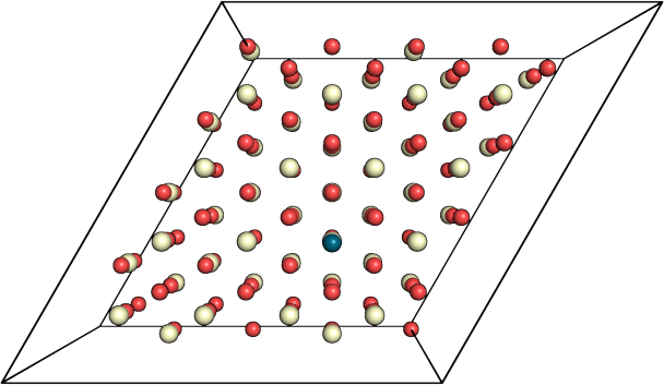
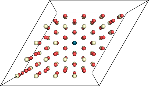
So as a showcase of the result of the code usage, one can see in figure 2 that I centralized the surface system based on the adsorbed atom I have.

 Figure 2: Upper, and bottom figures are before, and after adjustment, respectively.
Well, you can have the code by following this link. Please, feel free to join in if you would like to suggest any modification to the code.
That’s it, folks. I hope you like it as much as I do. :)
Take care.
Byeeeeeee.